Boot Pin 설정
내장 부트로더는 System memory에 저장되어 있고 이를 실행시키기 위해선 BOOT1핀을 0, BOOT0핀을 1로 한 상태에서 reset 해야 한다.

이를 위해 보드매뉴얼을 살펴본다.
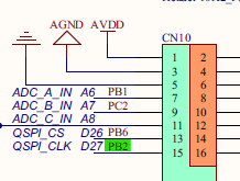
BOOT1핀은 default로 Solder Bridge가 Open된 상태이고 이 때 BOOT1 function은 사용되지 않는다고 한다. 그치만 PB2핀이 CN10을 통해 나와있으니 이 핀을 GND랑 연결해주면된다.


BOOT0 핀의 default state는 0이고 Morpho connector CN11을 통해 나와있으니 5번, 7번핀을 쇼트시키면 1로 만들 수 있다.


AN2606 System memory boot mode Application note 확인
여기서 나온 communication protocol은 호스트와 타겟이 패킷을 교환하기 위한 프로토콜로 표준 프로토콜은 아니고 ST사가 디자인한 프로토콜이다.

Application Note 초반엔 부트로더에 대한 general information이 나오고 그 다음엔 device family 별로 자세한 내용이 나온다.
STM32F42xxx 를찾아가니 부트로더 버전에 따라 설명이 나뉘어 있다.

Bootloader version 과 identification 섹션을 확인하고 메모리를읽어보니 부트로더 버전 V9.1이라는게 확인 됐다.


사용할 peripheral 선택 및 연결
AN2606 문서를 확인하면 ST사에서 만든 부트로더가 지원하는 통신방식은 USART, CAN, I2C, SPI, DFU 등 여러 방식이 있다. 그중에서 여기선 USART 방식을 사용하려고 한다.
다만 USART3을 사용하려고 보니 사용가능한 RX/TX핀이 지정되어 있는데 ST-Link 파트의 5핀 커넥터에 연결시 자동으로 잡히는 virtual COM port 는 PD8, PD9랑 연결된거라서 사용을 못하게 되었다.
따라서 USB to TTL converter가 필요하다.


다음과 같이 연결한다.
| STM32F429ZI | USB to ttl Converter |
| GND | GND |
| PB11 | TX |
| PB10 | RX |
Flash Loader Demonstrator 사용 Application 다운로드
아래 주소에서 STM32 Flash loader demonstrator 를 다운받는다.
https://www.st.com/en/development-tools/flasher-stm32.html
ST사 유틸리티는 기본 경로 C:\Program Files (x86)\STMicroelectronics 에 설치된다.
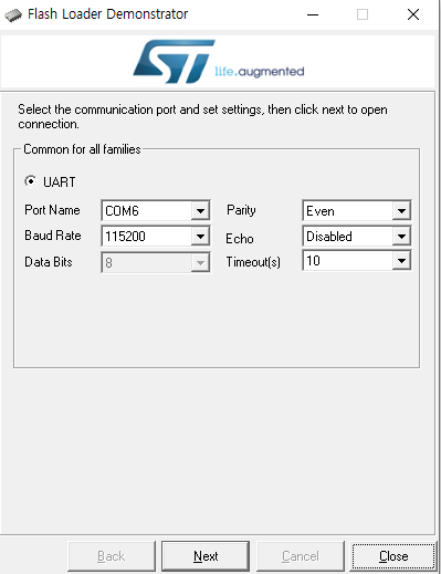
실행후 COM port를 선택한 후 Next를 누른다.

Boot 핀을 올바르게 설정후 Reset 한 상태가 아니라면 아래와 같은 경고가 뜬다.

Target is readable 이라고 뜬다. Next를 누른다.

Target과 Target의 Sector별 Address, Size를 제대로 읽은 모습이다. Next를 누른다.

다음 화면에서
Erase Flash,
Download binary(hex) file to the board
Reading from Flash memory
등 다양한 작업을 수행할 수 있다.

테스트를 위해 500ms 간격으로 LED를 토글하는 Application을 다운로드 해보려고 한다.
  while (1)
  {
    HAL_GPIO_TogglePin(LD1_GPIO_Port, LD1_Pin);
    HAL_GPIO_TogglePin(LD2_GPIO_Port, LD2_Pin);
    HAL_GPIO_TogglePin(LD3_GPIO_Port, LD3_Pin);
    HAL_Delay(500);
  }
프로젝트 우클릭 - Properties - C/C++ Build - Settings - Tool Settings - MCU Post build outputs - convert to intel Hex file

Apply 후 빌드한다.
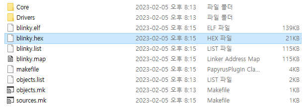
프로젝트 폴더를 찾아가면 .hex 파일이 생성된 것을 볼 수있다.

이 hex 파일을 USART 인터페이스를 통해 실행중인 부트로더로 보내고 부트로더는 이 파일을 스트림으로 받아서 Flash memory 0x0800 0000에 다운로드할 것이다.

Download to device 를 선택하고 download할 파일을 선택한 후 Next를 누른다.


Boot pin 쇼트시켰던걸 제거하고 reset을 해보면 LED가 깜빡이는 것을 볼 수 있다.
Reference : FastBit Embedded Brain Academy
+ User Application에서 다시 내장 부트로더가 있는 System Memory로 점프하는 방법도 있다. 아래 링크에서 해당 내용을 확인할 수 있으며, 그 때는 다음의 스텝을 따라야 한다.
https://stm32f4-discovery.net/2017/04/tutorial-jump-system-memory-software-stm32/
Steps for jumping to system memory
If you wish to just from main program to system memory at anytime, some important steps needs to be performed first:
- Find system memory location for specific STM32 in AN2606
- Set RCC to default values (the same as on startup) [Internal clock, no PLL, etc.)
- Disable SysTick interrupt and reset it to default
- Disable all interrupts
- Map system memory to 0x00000000 location
- Set jump location to memory location + 4 bytes offset
- Set main stack pointer to value stored at system memory location address
- Call virtual function assigned before
'임베디드 개발 > STM32 (ARM Cortex-M)' 카테고리의 다른 글
| STM32 ] 유저 버튼 고장 수리하기 (0) | 2023.04.09 |
|---|---|
| STM32 ] 커스텀 부트로더 (IAP) (6) | 2023.02.15 |
| STM32 ] Boot Configuration (0) | 2023.02.06 |
| STM32 ] Reset Sequence 이해하기 (8) | 2023.02.06 |
| STM32 ] 메모리 구조 (0) | 2023.02.06 |


